Knowledge about MODULAR PIPEWORK SYSTEMS
David Nguyen | ✉ ceo.kthjsc@gmail.com | 📱 +84 386 386 897
Posted on September 14, 2025
Pipework systems are the lifelines of modern production plants. They transport raw materials and products, convey exhaust air and extract dust. The applications are as diverse as the spatial requirements. This means that each pipework system is unique.
The modular system developed by JACOB combines easy assembly with numerous options for creating customised designs. This is how we achieve the right solution for every challenge. The idea originated around 100 years ago. As an alternative to manufacturing pipe systems individually and welding them together, our technicians and engineers developed a modular system made up of standard parts. With seals and pull-rings, the pipe components can be quickly assembled and disassembled. For the user this means: calculable project costs, outstanding product quality, quick installation, and short downtimes for maintenance work.
With more than 8,500 different standard products, our range covers practically all requirements. Customer-specific solutions are created by our experts in the customised production department. In combination with our advisory expertise, this makes us your one-stop shop for your complete pipework system. And on an international level too: with our subsidiaries in Europe and North America, 40 offices worldwide and eight warehouses around the globe, we are always close to hand.
How a Hydrocyclone Works: 3D Animation Explains Advanced Fluid Separation
David Nguyen | ✉ ceo.kthjsc@gmail.com | 📱 +84 386 386 897
Posted on September 29, 2025 | 🔗 Source: https://www.youtube.com/watch?v=IZsnGuE5G4k
Hydrocyclones are essential devices for phase separation in aqueous solutions, using the difference in gravity to separate solids or fluids within a bulk fluid. Unlike dry cyclones, these tools use centrifugal motion generated by tangential feeding to push heavier particles downward, where they are discharged. The no-moving-parts design makes them long-lasting and low-maintenance.
A high-fidelity 3D animation with advanced fluid simulation was created to illustrate in detail how hydrocyclones work, showing the precision of the separation process.
Parts of a Centrifugal Pump
David Nguyen | ✉ ceo.kthjsc@gmail.com | 📱 +84 386 386 897
Posted on September 25, 2025
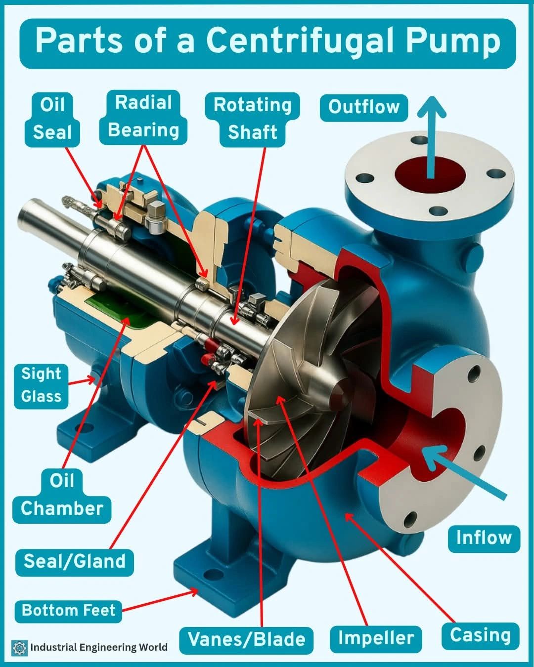
Centrifugal pumps are the heart of fluid movement in countless industries-from water treatment to chemical processing. But have you ever wondered what’s really going on inside? Let’s break down the main components that make this pump so powerful and efficient!…
1. Casing
This outer shell holds everything together and guides the liquid from the inflow to the outflow.
Think of it as the pump’s body armor!
2. Impeller
The spinning hero of the pump. It creates centrifugal force that propels the liquid outward, converting mechanical energy into kinetic energy.
3. Vanes/Blades
Attached to the impeller, they direct the liquid flow efficiently-maximizing pressure and flow rate.
4. Rotating Shaft
This connects the motor to the impeller. As it turns, it powers the entire pumping action.
5. Seal/Gland
Prevents liquid from leaking along the shaft-ensuring a tight, secure, and safe operation.
6. Oil Chamber & Oil Seal
Lubricates and protects the rotating components, reducing friction and preventing wear.
7. Sight Glass
Allows visual monitoring of the oil level-helping in predictive maintenance.
8. Bottom Feet
Provides stable mounting for the pump, ensuring vibration-free performance.
9. Radial Bearing
Supports the shaft and keeps it aligned while it spins under load.
10. Inflow & Outflow Ports
Inlet (inflow) draws liquid into the pump, and outlet (outflow) pushes the high-pressure liquid out.
Typical Pressure-Reducing Station: Components, Functions, and Purpose
David Nguyen | ✉ ceo.kthjsc@gmail.com | 📱 +84 386 386 897
Posted on September 21, 2025
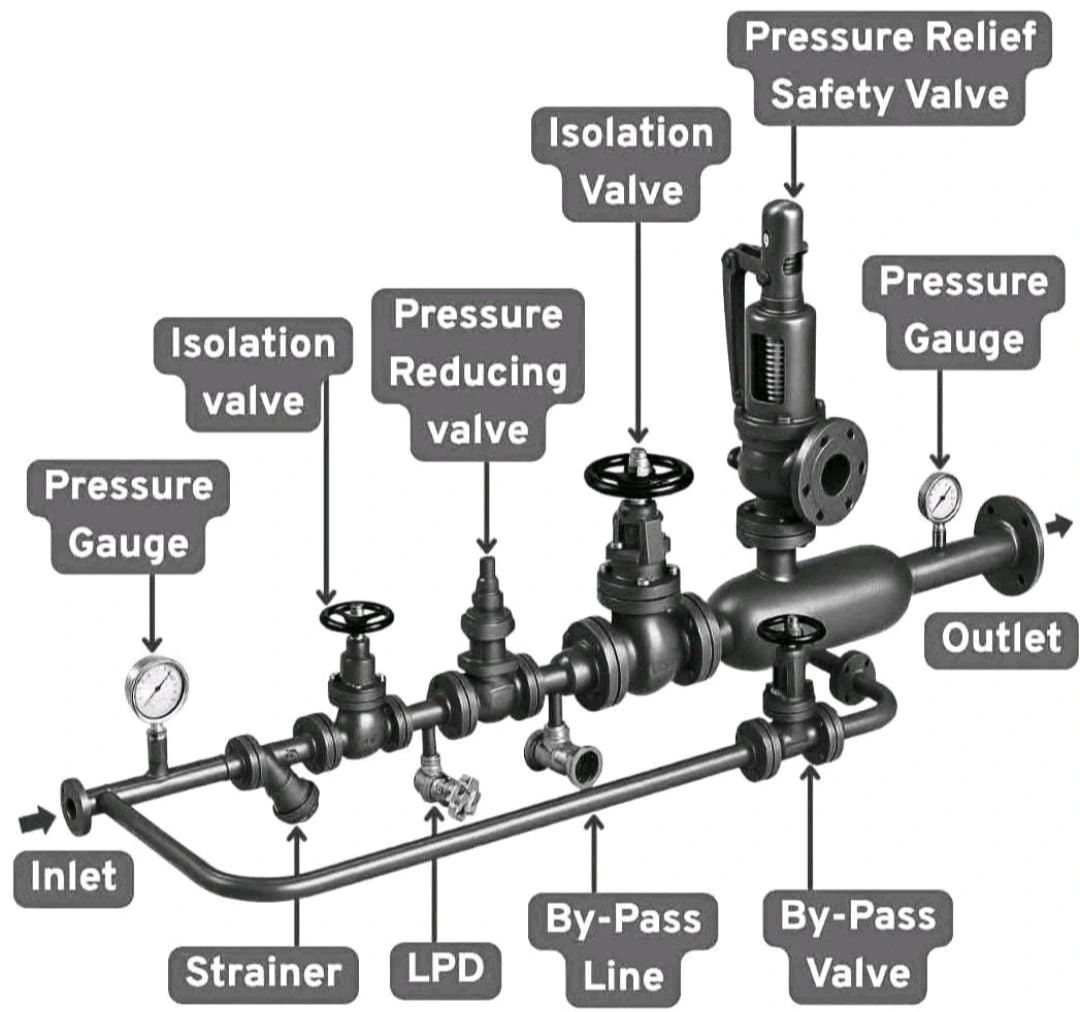
This diagram shows a typical pressure-reducing station used in piping systems, especially in steam or gas lines. Each part plays a specific role to control pressure, ensure safety, and maintain steady flow..
1. inlet
This is where high-pressure fluid enters the system.
2. strainer
Removes dirt, rust, or solid particles from the fluid. This protects downstream equipment and prevents clogging or damage to valves.
3. lpd (low point drain)
Located at the lowest part of the line, it drains condensate or fluid. Used during maintenance or startup.
4. pressure gauge (upstream)
Measures the pressure before the reducing valve. Used to monitor and ensure inlet pressure is correct.
5. isolation valve (before prv)
Used to manually stop flow for maintenance or emergency shutdown. Usually a gate or ball valve.
6. pressure reducing valve (prv)
Main control valve that reduces high inlet pressure to a lower set outlet pressure. Works automatically based on pressure settings.
7. isolation valve (after prv)
Allows isolation of the prv from the rest of the system. Helpful during repair or when using the bypass line.
8. pressure gauge (downstream)
Shows the pressure after reduction. Helps verify the prv is working correctly.
9. pressure relief safety valve
Protects the system by automatically releasing pressure if it becomes too high. Prevents damage to downstream piping and equipment.
10. isolation valve (safety line)
Lets you isolate the safety valve for maintenance. Usually locked open during normal use.
11. outlet
The end of the system where the regulated pressure fluid exits to downstream users or equipment.
bypass line section:
12. bypass line
An alternate path to keep flow going when the prv is under maintenance. Used for temporary operations.
13. bypass valve
Manually operated. Allows flow through the bypass line but doesn’t reduce pressure. Used only when needed.
purpose of this setup:
– reduces pressure safely and automatically
– protects downstream parts from high pressure
– allows for continuous operation even during maintenance
– ensures safe, efficient flow in steam, gas, or fluid systems
Commonly used in steam plants, refineries, chemical processing, and utility services.
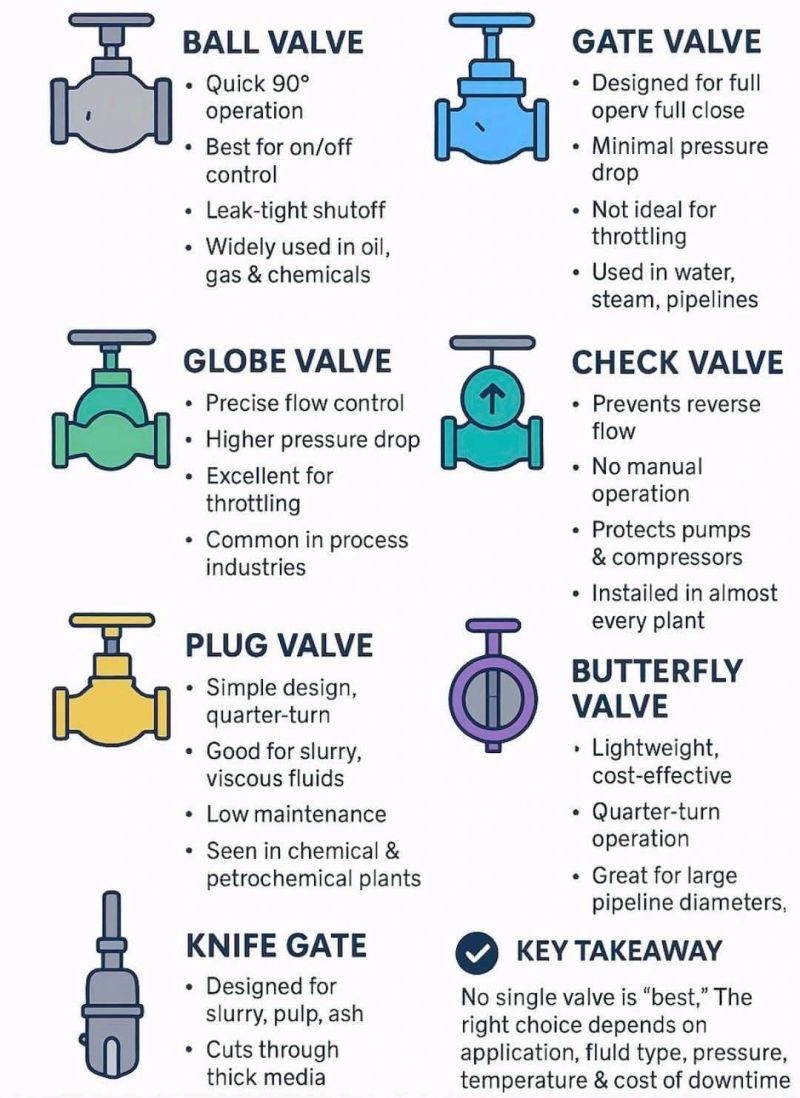
Understanding Different Types of Industrial Valves
David Nguyen | ✉ ceo.kthjsc@gmail.com | 📱 +84 386 386 897
Posted on September 14, 2025
In every plant – whether Oil & Gas, Chemicals, Pharma, or Utilities – valves are the gatekeepers of flow.
Yet many engineers and purchasers often ask: “Which valve is right for my application?”
Here’s a simple breakdown
1. Ball Valve
a. Quick 90° operation
b. Best for on/off control
c. Leak-tight shutoff
d. Widely used in oil, gas & chemicals
2. Gate Valve
a. Designed for full open/full close
b. Minimal pressure drop
c. Not ideal for throttling
d. Used in water, steam, pipelines
3. Globe Valve
a. Precise flow control
b. Higher pressure drop
c. Excellent for throttling
d. Common in process industries
Understanding Different Types of Impellers Pumps
David Nguyen | ✉ ceo.kthjsc@gmail.com | 📱 +84 386 386 897
Posted on September 07, 2025
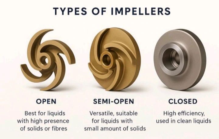
Open vs. Semi-Open vs. Closed Impellers – What’s the Difference?
In pump design, the type of impeller you choose directly impacts performance, maintenance, and longevity. Here’s a quick breakdown:
Open Impeller
Simple design – vanes attached to a central hub without sidewalls
Easier to clean & maintain
Best for handling solids or fibrous materials
▲ Lower efficiency & more wear; not ideal for high-pressure systems
Semi-Open Impeller
Vanes have a partial shroud on one side
Handles small solids while offering better efficiency than open types
Easier to manufacture & maintain
▲ Requires tighter clearance for performance – may need frequent adjustment
* Closed Impeller
Vanes are fully enclosed between two shrouds
Highest efficiency ideal for clean, low-viscosity fluids
Suitable for high-pressure systems
▲ Less tolerant to solids; more difficult to clean or inspect
▲ Typically requires tighter manufacturing tolerances.