PRODUCTS LIST

CONTACT US

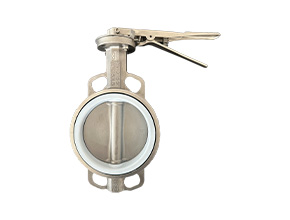
Wafer Butterfly Valve

More Detail

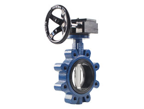
Lug Butterfly Valve

More Detail

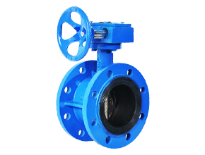
Flange Butterfly Valve

More Detail

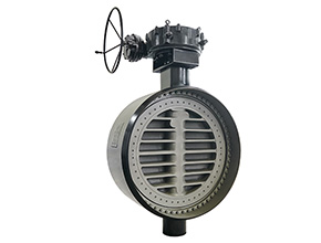
Weld Butterfly Valve

More Detail

Eccentric Butterfly Valve

More Detail

What Are Industrial Valves?

In industrial applications, valves play a vital role in controlling or regulating media movement in piping systems. The wide scope of industrial applications allows more varieties in valve design.

While most are for the stop-start mechanism, certain valves also have throttling capabilities. Additionally, valves are either manually operated or with the use of a gear that moves the actuator.

Any person engaging in the piping business should understand the importance of valves. Knowing the operation and maintenance of valves ensures that these can last longer. It also ensures that the entire piping process is without delays.

This article discusses everything you need to know about industrial valves. Included in this article are the different valve functions and the general valve parts. This article also discusses the commonly used valves in industrial applications.

There are three methods of making valves: cast, fabricated, and forged. This section will list compare the advantages and disadvantages of each method. To learn more about what takes place in each stage of valve production, read our Industrial Valve Manufacturing Process guide.

Cast Valve

The casting method starts by melting the metal material and pouring this into molds. The liquid material solidifies in the molds and then removed and polished.

  • Advantage

    Cast valves can be reused. They are also more cost-effective due to the lower production cost. This is the better option when the material is an alloy containing chrome, nickel, and molybdenum.

  • Disadvantage

    Metal shrinkage happens. There are more defects in cast-manufactured valves. These include tears, holes and porous surface. The regulations and specifications are less strict. What this means is shady manufacturers can produce valves of lesser quality.

Fabricated Valves

Fabrication is the process of cutting, forming, drilling or any type of machining and welding metal materials into finished products such as valves.

  • Advantage

    Fabricated valves can withstand high temperature and highly durable. It is also cost-effective. It is also highly customizable.

  • Disadvantages

    There is a post-fabrication process which is costlier. It is also prone to high maintenance costs. Once the metal loses ductility, it develops brittle fractures.

Valve Functions

Valves play a pivotal role within the piping system, and each valve has a different role to play. To summarize, there are five functions for industrial valves. While it is possible that there are overlapping functions for one type. Commonly, most are more efficient in just one or two functions at a time.

  • Stop & Start: Valve either allows media to pass or obstructs media flow so it won’t pass.
  • Fluid Flow Control: The valve controls the media flow. Valves that have this function can be multidirectional. These are also multiports, meaning, they have more than exit points. Such characteristics allow the media to move in different directions.

  • Pressure & Flow Regulation: Through the opening and closing, valves can adjust or maintain the pressure and flow within the pipes.

  • OK did you sleep updated on the tasks it actually 26 September other ones finish today speed of them days because we need to record yes Stacy looks like yes exactly she didn’t check the message go to see inch 8 feet we go to see HBAN firstPressure & Vacuum Relief: Valves can relieve over-pressure, especially when there is media flow. It can also increase pressure when vacuum is present.

  • Throttling: Some valves allow partial opening so a certain percentage of media can flow through.

Valve Parts

Industrial Valve Parts And Components

The industrial valve is a collective set of smaller parts. There are internal and external parts. While specific valve types contain certain components definitive to that design, all industrial valves share major valve components. This section will discuss the different valve parts.

Take a look at a cross-section of a valve below to view the major components:

Body

The body houses the internal parts of the valve, including the trim. This is also the passageway for the fluid. Industrial valve manufacturers produce this as either of the three: cast, forged or fabricated. The body also connects the valve on both ends to the pipe system.

The body valve designs depend on the valve functions as well as the size of the pipes to which the valve attaches. That being said, there are three major types:

  • Full Bore

    The diameter of the valve and the pipes are the same. This has very little pressure loss. This design is preferred when there is a need for internal valve cleaning or inspection. Also, choose such a design when the pressure drop or pressure loss affects pump performance.

    Full bore body valves reduce material build-up due to the separation of particles in thicker media.

  • Reduced Bore

    The internal diameter of the valve on both ends is smaller than that of the pipe. Additionally, when the pressure drop is not a major consideration, use this type. The reduced bore, also known as the standard bore, is cheaper and lighter.

  • Crossflow Bore

    The crossflow body or the split section body is commonly seen in gate valves, plug type valves. With this design, there is a significant backflow when the plug or disc is at the closing position. Used in throttling, media moves in a more controlled manner in this body valve design.

industrial valve parts

Bonnet

Some industrial valve manufacturers call this part as the cover. There is much emphasis on the bonnet and body connection because the majority of leaks come from this. Split body ball valves don’t have a bonnet as the body is cut into half lengthwise.

The two functions of the bonnet are:

It houses the internal parts of the valves.

It supports the stem since it is in the of the bonnet in many valve types.

Valve Trim

The valve trim refers to the collective valve parts that come in contact with the flow media. These are the disc, the valve seat, and stem. Take note, some valves may have additional parts, but generally speaking, these three are always present in most valves.

The type of seat and disc, along with the placement of the disc in relation to the seat, determine the valve trim performance. It is also the combination of the disc, seat, and stem that determines the movement and control of the valve.

  • Disc

    The disc has alternative names depending on the type of valve. Ball and gate are two other names for the disc. This part can function as a throttle or to stop/permit the flow of media into the valve to the pipes.

  • Seat

    The seat provides the cushion for the disc. Seal rings are its other name. Some types of valves have one seat while others have two or more.

    The higher the number of seats, the better sealing. Multiport valves have more seats since these have more than one exit. Some seats are integrated into the valve structure. Others are replaceable.

    The quality of the valve seat directly affects the effectiveness of leakage prevention. Depending on the requirements like the type of flow media, temperature and pressure gauges, and the likes, valves are either elastomer like Teflon or metal.

  • Stem

    The stem is the shaft that connects the disc to the actuator. This part supplies the motion needed to open or close the disc. The opening and closing movements are either linear like the gate or globe valves, or rotational like the butterfly and ball valves.

Bolts

Bolts hold one valve part to another, for example, the bonnet to the body. The bolts make the seal tighter.

Actuator

The actuator goes by many names such as wheels, levers, and handles. More often than not, the names follow the design of the actuator. Gate and globe valves have manual handwheels as actuators. On the other hand, ball, plug and butterfly valves have levers that act as actuators.

While manual actuators are common, there circumstances that automation or power is the ideal way to actuate.

There are issues with valve location such as being remote.

Time does not allow the valves to open quickly via manual methods.

The valve is large and the pressure is too high; manual opening becomes risky.

Packing

This is also called the gasket. Packing functions as a seal between the stem and the bonnet. This plays an important role as the proper installation of the packing increases the life service of the valve.

Installed too loose, the valve leaks. Installed too tight, the valve cannot move. Packing, in other words, reduces damage and increases the sealing capability of the valve. It has five components, namely the gland follower, the gland, the stuffing box, and the backseat.

Yoke

The yoke is the arm that connects the body and bonnet to the actuator. Made as a one-piece with the bonnet, the yoke should withstand the force applied to the actuator. The yoke contains the nuts and bushing that act as connectors to other parts of the valve.

Types of Valves

What Are Industrial Valves Used For

There are nine major types of valves on the market. Below is a table that shows these valve types and their matching functions. To learn more about each valve, read our 9 Types of Industrial Valves guide that explains the different types in detail.

Functions of Different Industrial Valves
Isolation Valves Non-Return Valves Pressure Relief Valves Regulation Valves
Type of Industrial Valves Gate Valve Check Valve Pressure Relief Valve Gate Valve
Ball Valve Butterfly Valve
Butterfly Valve Ball Valve
Pinch Valve Plug Valve
Plug Valve Pinch Valve
Globe Valve Needle Valve

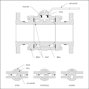
Ball Valve: Meaning, Design and Application (With Diagram)

Ball valve is part of the quarter turn valve family. It employs a hollow ball-shaped disc for the start and stop mechanism. Because of its design, the ball valve is one of the quickest valves to open or close.

Ball valve is suitable for fluid, gaseous and vapor applications that need bubble-tight shutting down. High pressure and temperature applications are also suitable for this kind of valve only if the seat is metal.

industrial ball valve parts

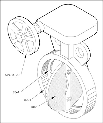
Butterfly Valve: Meaning, Design and Application (With Diagram)

Butterfly valve has a disc that can be flat or concave. This disc prohibits media flow when the valve is closed. The stem adds support by being bored into the disc or attached at one side of the disc. The butterfly valve is also part of the quarter turn family of valves.

This valve is often used in water and gas applications as well as processes with pipes with large diameters. Slurry applications are suitable for butterfly valves. This is also suitable for cryogenics and vacuum services.

industrial butterfly valve parts

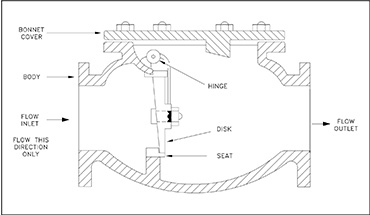
Check Valve: Meaning, Design and Application (With Diagram)

Check valve relies on internal pressure to open or close. Otherwise known as a non-return valve, prevention of backflow is the main use of this type of valve.

Check valves are used in applications that need backflow prevention such as pumps and compressors.

industrial check valve parts

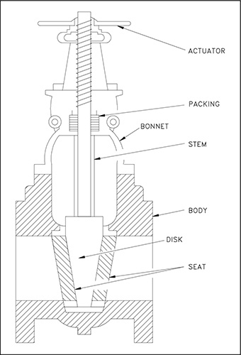
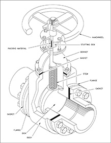
Gate Valves: Meaning, Design and Application (With Diagram)

Gate valve belongs to the shut off/on valve family. But, its disc movement is linear. Gate valve uses a gate or wedge to shut off or on media flow.

Gate valves are great shut off/on valves for any application. The knife valve is used for slurries and powder media.

gate valve parts

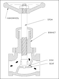
Globe Valves: Meaning, Design and Application (With Diagram)

Globe valve is a plug type, linear motion valve. Shut off/on and fluid flow regulation are its best assets. Like the gate valve, the disc moves up unobstructedly to allow the flow of media. Because of its design, globe valves have great throttling capabilities.

Globe valves perform well when the major concerns are leakage. High point vents and low point drains use this kind of valves. Also, gate valves work when the pressure drop is not a concern.

industrial globe valve parts

Needle Valves: Meaning, Design and Application (With Diagram)

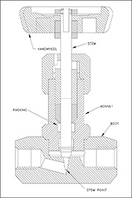
Needle valve looks almost the same as the globe valve except that, instead of a globe-like disc, the disc is needle-like. Still part of the quarter turn family, the needle valve gives a more accurate control in smaller piping systems.

Needle valves are used in instruments that need fuller control for fluid surge, the precision of fluid flow or if there is a need for small quantities.

needle valve parts

Pinch Valves: Meaning, Design and Application (With Diagram)

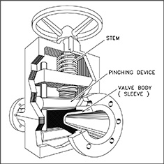
Also called the clamp valve, pinch valve is a linear motion valve used to stop or start the flow and to regulate it. A pinch tube using a pinch mechanism acts as the disc that controls the fluid flow. The linear motion allows unobstructed flow of media.

Mostly, pinch valves are used for unrestricted fluid flow. This type of valve is most suitable for slurry applications.

pinch valve parts

Plug Valves: Meaning, Design and Application (With Diagram)

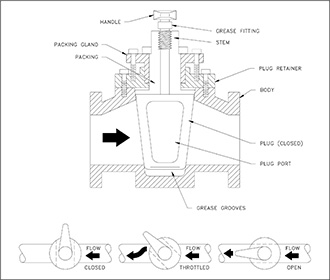
Plug valve belongs to the quarter turn family. It acts as a bubble tight shut-off and on capabilities. Relatively, it is called the plug valve because the disc is shaped like a tapered plug or cylinder, making it very effective in obstructing fluid flow through the valve.

Plug valve is an effective tight shut off or on valve. Almost all applications including sewage, slurries and mud can use this valve. High temperature and pressure applications are also suitable.

plug valve part

Pressure Relief Valves: Meaning, Design and Application (With Diagram)

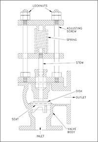
As its name connotes, pressure relief valve releases pressure from the pipelines. Its main purpose is to protect the equipment in an overpressured event or to increase pressure when there is a drop. This valve is effective when back pressure is not a major consideration.

pressure relief valve parts

Valve Opening & Closing

Valve Opening & Closing

There are three ways of opening and closing the valve: linear, rotational and quarter turn. Check out the table below that shows the valves and the methods of opening or closing:

Valve Opening Linear Valves Rotational Valves Quarter Turn Valves
Gate Valve No No Yes
Globe Valve No No Yes
Ball Valve Yes No No
Butterfly Valve Yes No No
Swing Check Valve Yes No Yes
Lift Check Valve Yes Yes Yes
Tilting Disc Check Valve Yes Yes Yes
In-line Check Valve Yes Yes Yes
Stop Check Valve Yes Yes Yes

Here is a video of a gate valve opening and closing. Gate valves belong to the linear motion valves.

The upward and downward movement of the disc either closes, opens or throttles the media flowing. Because of the thread design of these types of valves, opening and closing of the valve is slower compared to the other two types.

On the other hand, the butterfly valves is a rotational type as seen in this video.

A rotational valve type has a hinge pin that holds the disc. Once the hinge pin releases the valve, it closes the entry point. Turning the actuator in the other direction tightens the pins. This, in turn, raises the disc to allow media to enter the valve.

Meanwhile, ball valves are quarter-turn motion valves. Here is a video of a ball valve opening and closing.

A quarter-turn or 90°-turn valve only needs that much angle to open or close the valve. Compared to the linear and rotational types, this has a much faster mechanism.

Valve Actuators

Look at the different valve actuation types.

Types of Operation
Manual Valve Power Valve Automation Valve
Hand Wheel Valves Electric Motor Valves Not applicable
Hand Lever Valves Air/Pneumatic Valves Not applicable
Gear Wheel Valves Hydraulic Valves Not applicable
Chain Valves Solenoid Valves Not applicable

There are three major types of actuation operation: manual, power and automation.

Manual going

Manual actuation means the actuator can be opened or closed by hands. Manually driven actuators are the best choices when there is flexibility in positioning the valves. Also, this is the best option when power is too far off to reach the valves along the pipeline.

Manual actuators are not the best choices when the valve is too big. However, hammer or gear heads can aid the actuator if used in larger applications.

Power

Actuators use different power methods for the opening and closing of the valve.

  • Electric Motor

    Electric motors are the machines used in actuators. The electric motor connects to the gear train, that attaches to the actuator. The electric motor aids it. It is also possible that the motor directly opens or closes the actuator.

  • Pneumatic

    This type uses compressed air pressure to directly open or close. A piston attaches to the valve stem. This delivers the air pressure that transmits to the stem, thereby moving it to close or open.

  • Hydraulic

    This uses the hydraulic system to open large valves. The principle behind this is fluid pressure. The hydraulic system either use water or oil to create pressure. Without the hydraulic fluid, the pressure in the spring holds the valve in the closed position.

    The actuator opens when the hydraulic fluid enters the spring chamber. When the hydraulic pressure is higher than the spring pressure, the piston and the stem move up and opens the valve, and vice versa.

  • Solenoid

    Solenoids are electromagnet coil that, when there is a power source connection, creates a magnetic field. This magnetic field pulls up the plunger attached to the coil. The T-shaped plunger acts as the actuator. Solenoid actuators are best in not-so-large applications because the power source stacks up expensively.

Automation

Automatic actuators do not use external force to open the valves. Rather, it uses internal fluid or gas pressure.

Valve Stems

The valve stem receives the actuator motion so that the valve can open, close or throttle. There are five types of valve stems based on the orientation of the thread, as well as the movement of the stem.

Rotary Stem

Quarter-turn valves such as the butterfly valve, plug valves as well as the ball valves have this kind of stem. For the valve to open, the stem only needs to turn a quarter.

Sliding Stem

Contrary to the other stems in this list, the stem does not rotate. Rather, it slides to open or close the valve. Applications that need fast opening require this stem design. Control valves with pneumatic and hydraulic actuators are such examples.

Non-Rising Stem

The non-rising stem has its threads inside the valve. As its name connotes, the stem becomes stationary. Opening and closing of the valves mean the valve disc travels up or down in rotation along the stem.

The design exposes the stem to the media when the valve is open. That being said, the media also impacts the stem. In connection with this, two issues arise: how the design affects stem durability, and how the design affects pressure levels.

Non-rising stems are used when there is more linear movement, given the limited valve and pipe diameter.

Rising Stem with Inside Screw

Similar to the previous type, the thread is also inside the body. The stem exposed to the external environment is smooth. However, in contrast, rotation makes the stem and actuator rise to open and down to close. Once the stem rises, the body exposes the threads to the media. This can cause erosion to the threads, creating leaks over time.

Rising Stem with Outside Screw

This design, more popularly known as OS & Y, is similar to the previous design as the stem rises once the valve opens and vice versa. However, the difference is that the thread is in the exposed part of the stem. The one in contact with the valve is smooth.

The rising of the thread can be one of the two designs:

1. The stem has an attached handwheel that goes up together for opening the valve.

2. The handwheel rotates and the stem rises alone.

Valve Stems

Valve end connections refer to the connection of the valve to the pipe system. There are five types of these connections.

Threaded

The threaded type needs also to have the corresponding thread in the pipes so they fit together. The valve end has the female thread and the pipe end, the male thread.

Both ends must follow the same standards. Take note, though, there are several standards available the National Pipe Thread Tapered (NPT), the British Standard Pipe Taper Threads (BSPT) and the British Standard Parallel Pipe Threads (BSPP) .

The threaded type can be one of two types: the straight threaded and the tapered threaded. The straight threaded ends have a soft seal like an O-ring or a washer placed between the pipe and valve connections. On the other hand, the tapered threaded type does not have that soft seal.

Flanged

Flanged-end valves are easy to install and remove. This connection uses bolts to connect the valve to the pipeline. A gasket is installed between the two connections to ensure a tight seal.

Flanged connections have several industrial standards to follow. Examples are ANSI/ASME or the American National Standards Institute and American Society of Mechanical Engineers, respectively. There is another standard that industrial valve manufacturers follow called DIN, when translated to English it means German Institute for Industrialization.

Butt-Welded

The outer edges of the pipe and valve when stacked together create a bevel or valley. This is where the welding is done. The bevelling creates a more uniformed thickness to the pipe-valve connection. Often done on steel pipes and valves, pipes with this type of valve can endure high pressure and temperature.

Socket-Welded

The valve has a wider diameter than the pipe diameter so the pipe is inserted into the valve. Closing of the rim is done by welding it. This type of connection is permanently closed and leak free.