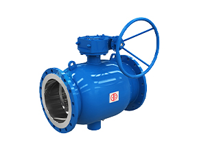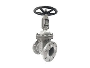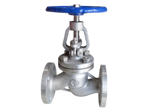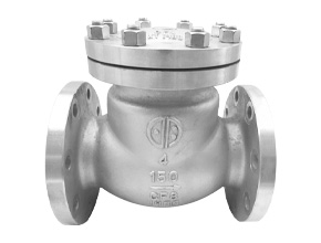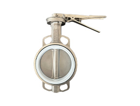
Industrial Butterfly Valves
Size Range: DN50-DN4000
Pressure: PN6/10/16/25/40 Mpa 150/300 Class

Forged Steel Valve
Size Range: DN15-DN100
Pressure: PN16-PN25/PN40/PN63/PN100/PN160/PN250
Valve Functions
Valves play a pivotal role within the piping system, and each valve has a different role to play. To summarize, there are five functions for industrial valves. While it is possible that there are overlapping functions for one type. Commonly, most are more efficient in just one or two functions at a time.
-
Stop & Start: Valve either allows media to pass or obstructs media flow so it won’t pass.
-
Fluid Flow Control: The valve controls the media flow. Valves that have this function can be multidirectional. These are also multiports, meaning, they have more than exit points. Such characteristics allow the media to move in different directions.
-
Pressure & Flow Regulation: Through the opening and closing, valves can adjust or maintain the pressure and flow within the pipes.
-
OK did you sleep updated on the tasks it actually 26 September other ones finish today speed of them days because we need to record yes Stacy looks like yes exactly she didn’t check the message go to see inch 8 feet we go to see HBAN firstPressure & Vacuum Relief: Valves can relieve over-pressure, especially when there is media flow. It can also increase pressure when vacuum is present.
-
Throttling: Some valves allow partial opening so a certain percentage of media can flow through.
Valve Actuators
Look at the different valve actuation types.
| Types of Operation | ||
| Manual Valve |
Power Valve |
Automation Valve |
| Hand Wheel Valves | Electric Motor Valves | Not applicable |
| Hand Lever Valves | Air/Pneumatic Valves | Not applicable |
| Gear Wheel Valves | Hydraulic Valves | Not applicable |
| Chain Valves | Solenoid Valves | Not applicable |
There are three major types of actuation operation: manual, power and automation.
Manual going
Manual actuation means the actuator can be opened or closed by hands. Manually driven actuators are the best choices when there is flexibility in positioning the valves. Also, this is the best option when power is too far off to reach the valves along the pipeline.
Manual actuators are not the best choices when the valve is too big. However, hammer or gear heads can aid the actuator if used in larger applications.
Power
Actuators use different power methods for the opening and closing of the valve.
-
Electric Motor
Electric motors are the machines used in actuators. The electric motor connects to the gear train, that attaches to the actuator. The electric motor aids it. It is also possible that the motor directly opens or closes the actuator.
-
Pneumatic
This type uses compressed air pressure to directly open or close. A piston attaches to the valve stem. This delivers the air pressure that transmits to the stem, thereby moving it to close or open.
-
Hydraulic
This uses the hydraulic system to open large valves. The principle behind this is fluid pressure. The hydraulic system either use water or oil to create pressure. Without the hydraulic fluid, the pressure in the spring holds the valve in the closed position.
The actuator opens when the hydraulic fluid enters the spring chamber. When the hydraulic pressure is higher than the spring pressure, the piston and the stem move up and opens the valve, and vice versa.
-
Solenoid
Solenoids are electromagnet coil that, when there is a power source connection, creates a magnetic field. This magnetic field pulls up the plunger attached to the coil. The T-shaped plunger acts as the actuator. Solenoid actuators are best in not-so-large applications because the power source stacks up expensively.
Automation
Automatic actuators do not use external force to open the valves. Rather, it uses internal fluid or gas pressure.
Valve Stems
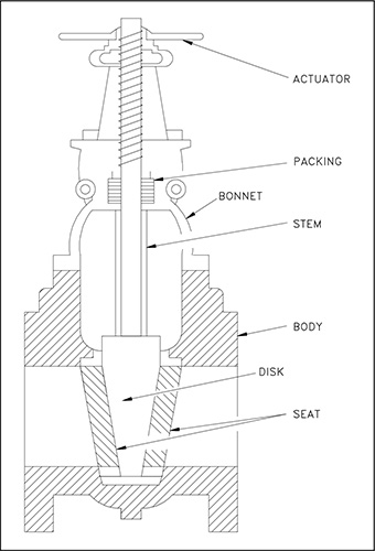
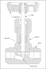
The valve stem receives the actuator motion so that the valve can open, close or throttle. There are five types of valve stems based on the orientation of the thread, as well as the movement of the stem.
Rotary Stem
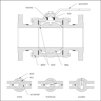
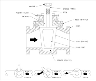
Quarter-turn valves such as the butterfly valve, plug valves as well as the ball valves have this kind of stem. For the valve to open, the stem only needs to turn a quarter.
Sliding Stem
Contrary to the other stems in this list, the stem does not rotate. Rather, it slides to open or close the valve. Applications that need fast opening require this stem design. Control valves with pneumatic and hydraulic actuators are such examples.
Non-Rising Stem
The non-rising stem has its threads inside the valve. As its name connotes, the stem becomes stationary. Opening and closing of the valves mean the valve disc travels up or down in rotation along the stem.
The design exposes the stem to the media when the valve is open. That being said, the media also impacts the stem. In connection with this, two issues arise: how the design affects stem durability, and how the design affects pressure levels.
Non-rising stems are used when there is more linear movement, given the limited valve and pipe diameter.
Rising Stem with Inside Screw
Similar to the previous type, the thread is also inside the body. The stem exposed to the external environment is smooth. However, in contrast, rotation makes the stem and actuator rise to open and down to close. Once the stem rises, the body exposes the threads to the media. This can cause erosion to the threads, creating leaks over time.
Rising Stem with Outside Screw
This design, more popularly known as OS & Y, is similar to the previous design as the stem rises once the valve opens and vice versa. However, the difference is that the thread is in the exposed part of the stem. The one in contact with the valve is smooth.
The rising of the thread can be one of the two designs:
1. The stem has an attached handwheel that goes up together for opening the valve.
2. The handwheel rotates and the stem rises alone.
Valve Stems
Valve end connections refer to the connection of the valve to the pipe system. There are five types of these connections.
Threaded
The threaded type needs also to have the corresponding thread in the pipes so they fit together. The valve end has the female thread and the pipe end, the male thread.
Both ends must follow the same standards. Take note, though, there are several standards available the National Pipe Thread Tapered (NPT), the British Standard Pipe Taper Threads (BSPT) and the British Standard Parallel Pipe Threads (BSPP) .
The threaded type can be one of two types: the straight threaded and the tapered threaded. The straight threaded ends have a soft seal like an O-ring or a washer placed between the pipe and valve connections. On the other hand, the tapered threaded type does not have that soft seal.
Flanged
Flanged-end valves are easy to install and remove. This connection uses bolts to connect the valve to the pipeline. A gasket is installed between the two connections to ensure a tight seal.
Flanged connections have several industrial standards to follow. Examples are ANSI/ASME or the American National Standards Institute and American Society of Mechanical Engineers, respectively. There is another standard that industrial valve manufacturers follow called DIN, when translated to English it means German Institute for Industrialization.
Butt-Welded
The outer edges of the pipe and valve when stacked together create a bevel or valley. This is where the welding is done. The bevelling creates a more uniformed thickness to the pipe-valve connection. Often done on steel pipes and valves, pipes with this type of valve can endure high pressure and temperature.
Socket-Welded
The valve has a wider diameter than the pipe diameter so the pipe is inserted into the valve. Closing of the rim is done by welding it. This type of connection is permanently closed and leak free.


